Pages

2022-04-21

C4000XG Part 1

 The C4000XG has been sold to CenturyLink customers as a "modem" for their fiber tier service.


CenturyLink often sells it to customers for $20 or less, but it is available on Amazon for over $200.

WHY ARE THERE 84 REVIEWS?!?!

I don't know who would buy a used C4000XG because while it works for some people (probably people who never touch it after the install tech leaves), it is full of software bugs. What kind of bugs you might ask? Well to start, it has a nasty habit of factory resetting itself once a month, though surprisingly the customer PPPoE credentials get preserved. Want to disable the router and use it as a plain old Wireless Access Point? Don't reboot it because DHCP gets re-enabled on every boot. Also there is a strange issue where some devices can't complete their DHCP handshake with the real router...

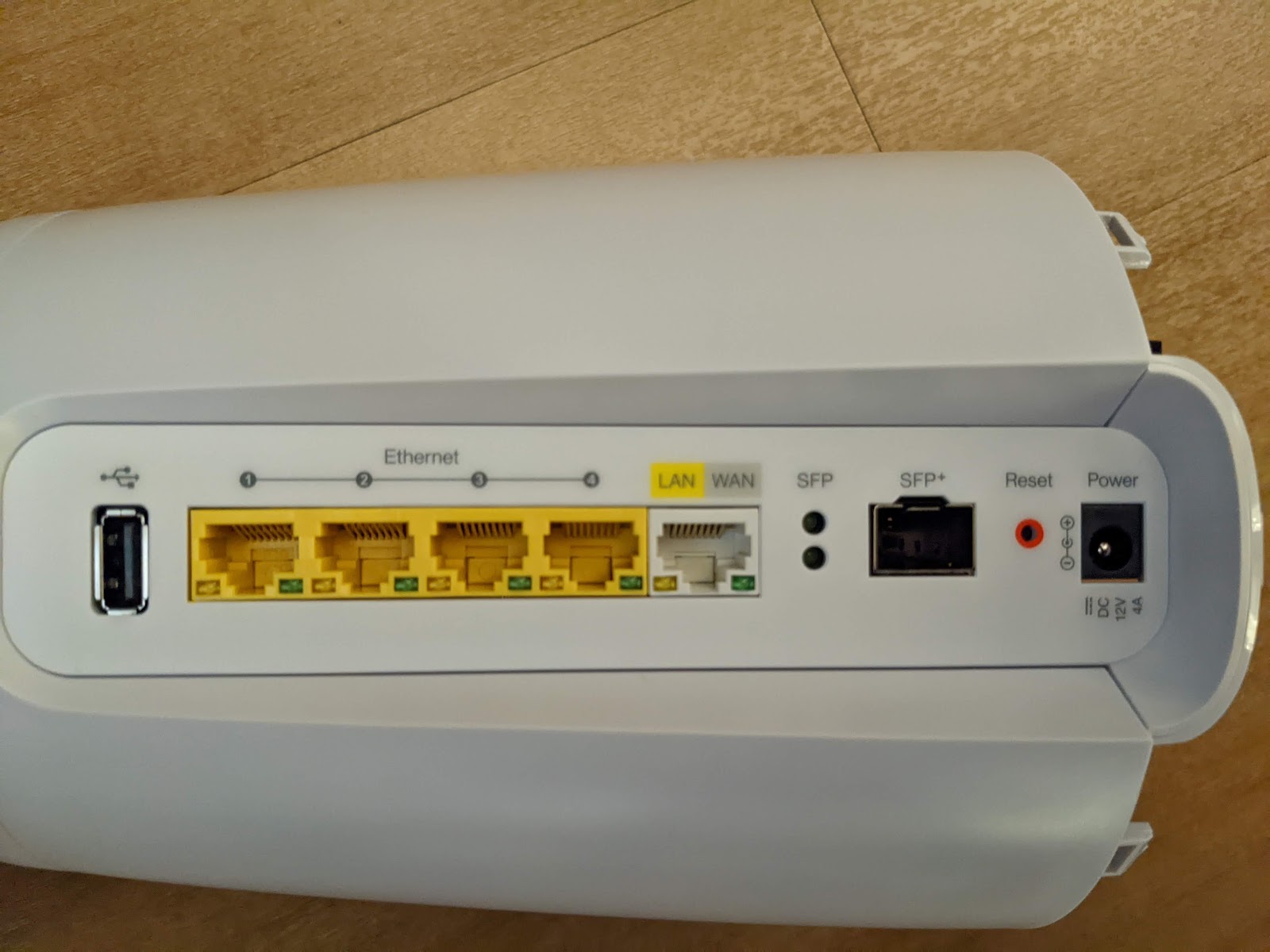
Ya ok... well if it so bad, why write this blog? Because the AX (WiFi-6) wireless radio is amazing. At least with a small number of devices, it seems to beat out a WiFi-5 Ubiquiti access point for cutting through the noise. I suspect due to the antenna layout. It also interestingly has an SFP+ port, possibly CenturyLink hoped to replace the ONT?

Cool, so just throw OpenWRT on it and... oh no. There is no OpenWRT image for this device. In fact, I haven't been able to Google any information about it's guts other than the FCC docs (fcc.gov).

So ladies and gentlemen, I present to you a sneak peek of the inside.


Isn't it pretty? ... *Crickets*. Ok ok, so I am mostly including an inside shot of the bottom to show others how to non-destructively take this sucker appart. Two screws must first be removed from under the rubber foot on the bottom (not shown). The screws are at the top and bottom of the CenturyLink Sticker, the rubber foot doesn't seem to be well attached in those locations so some gentle prying gives just enough room to get the screws out. Then 7 retention clips hold the grey bottom to the white body. Slipping a credit card through the vent slots easily releases the clips and with a little wiggling (the last one was stubborn) the bottom was removed.

Revealing...

Bunch of wires leading to the circular antenna in the top of the housing.

The cutout in the heatsink above the capacitor appears to be a serial connection with header pins labeled: TX, GND, VCC, RX

Annoyingly the back plate

Is also held in with 6 retention clips and hides 2 screws holding the circuit board in place. Three can be easily found under the heatsink on one side, but the other three... only one can be accessed.

The easiest way I found to remove the plate was to use my finger with my right hand to release the top clip and simultaneously use a spudger with a pointy tip with my left hand to release the opposing clip that can just barely be seen under the black plastic. Once that first pair of clips are released you can let go and then use the spudger to release the second clip on the right side. Then because the opposing clip is not accessible, twisting and futzing with the plate to make it come free on it's own. Finally, using a flat spudger to wedge in behind the plate on the outside, a second long pointy spudger can be used to "stab" behind the last clip on the right side and force it free. Then again futzing with the plate to free the opposing clip.

It took me probably 20 minutes to get it free, but I also didn't know the tricks above.


For now the last picture I will leave you with is the two screws that are next to be removed.


At this point I was done for the night, till next time when hopefully I have more information about what is inside...

2021-05-20

OhmPlug

I had talked with OhmConnect support earlier this year about a product that they had mysteriously added to their website without even a picture of the actual device. Just this smiling logo:


It was listed at a higher cost than the TP-Link product line and without any specification, though they are now listed on the OhmConnect Store.

They claimed at the time that the OhmPlug would feature better integration with OhmConnect (Their load shedding business), "a near-zero vampire draw", and "nice energy monitoring capabilities built in."

I was intrigued, but wasn't quite interested in being a beta tester of such a product since there was no picture of the device and while the OhmPlug app existed on the android store it looked... rough.

So several months pass, they release a new store site featuring a small photograph of the plug. So I bought one to review. Then I waited and waited for two weeks while the tracking number I had been given said UPS was still waiting for the package. Suspicious. I reached out to support and they assured me it shipped and would be here any day. I waited another week, no change to the tracking number. So I reached out again and they too agreed that something must have gone wrong so they canceled the order and reissued it. I got a new tracking number and behold the next day UPS said they had received the package. A few days later I received a small bubble wrap envelope with a small nondescript box inside and a packing slip.

Also interestingly the box is smaller than the dimensions on their store page.

The plugs actual dimensions are 1.9" deep X 3.1" wide X 1.45" tall.
If you exclude the prongs, its only 1" deep.

There is an included pamphlet pointing you at  https://www.ohmconnect.com/ohmplug

The back of which includes the specifications and legaleeze. Make sure you "Long oress"

The back of the plug includes the usual interesting bits about the "F2s101-US". Most notably that it is UL Listed. Bonus points to anyone that can figure out who SWE is that this is "Manufactured For". The firmware is made by SmartLife so maybe thats what the S is? I also adore the lowercase x in MAx.


Next I took some readings on the vampire draw (0.5W when off, 1.1-1.5W when on). This is a bit higher than the TP-Link devices which are about 0.4W off and 0.8W when on. So already, if you don't intend to use the energy monitoring feature on this device, I would not buy it.


So lets add our plug. Opening the app, there is a splash screen I couldn't get a picture of with the OhmConnect logo stretched excessively vertically.


Clicking Add Device asks you for a wifi password and nagging you to make sure you are on 2.4Ghz. Its a little inconvenient but par for the course with smart devices. But then I saw this:


And I'm like "Uh.. No". Apparently I have a neighbor with a bluetooth enabled wake up light. I fought with this for probably half an hour before realizing that what is happening is the OhmPlug is WiFi only and this "Wake Up Light" is bluetooth. Apparently pairing a bluetooth device takes precedence and you CANNOT pair the OhmPlug unless you can get away from the device or you just disable bluetooth.

After doing that it tells you how to press the button to put it in pairing mode and then it is no problem. 

Note that if you hold the button again it blinks slower and goes into some kind of firmware recovery mode. This is how I identified the firmware vendor as SmartLife.


I did a quick test charging some batteries. The kill-a-watt was reading 1 watt different from the app which makes sense since the OhmPlug draws 1 watt when on.


Next I performed a SuperScientific™ experiment with my TP-Link plugs which have a small but known power draw. They revealed that the OhmPlug does agree within 1W of the Kill-A-Watt with one ANNOYING caveat. The OhmPlug cannot read anything less than 3W. Anything less and it just says 0W. Also annoyingly the app seems to stop refreshing randomly which if you are trying to see how much power something uses in different modes is really annoying. There is also a 4 second or so delay on the reading in the app which compounds the problem.


We'll have to see how its daily counts of watthours compares to the kill-a-watt. I would like to get daily totals as that is something the kill-a-watt cannot do. I'm hesitant since on one screen it says I've used 0.04kWh today but the other says 0.00. 

In short I probably wouldn't buy more than one. The app leaves something to be desired and I'm disappointed by the 3W minimum reading while it draws over 1w while on (Why do none of these companies use latching relays??).

2020-08-01

Goovi EV-693 Repair

For the last 9 months or so our go-to hand vacuum has been the Goovi EV693. We purchased it after moving into a smaller space and ditching our full sized upright Dyson. Moving made the budget tight and so we were looking to optimize our vacuum purchase. Research lead us to the high reviews of this cordless stick with a sticker price less than half that of a Dyson. We figured if it didn't hold up we would invest in a better unit.

To our surprise this unit operated FLAWLESSLY for months. We also have a Neato Botvac-connected that handles our day to day cleaning so the Goovi would come out for spills or getting into nooks too small for a robo-vac. We love this vacuum but thought we killed it when we had to clean up a large quantity of baking soda. My first thought was that we got baking soda in the motor and too much friction was causing it to trigger an over current device. The unit would run for about 30 seconds but become very finicky where the motor would cut out randomly and run for only short durations. During this the vacuum would sometimes turn itself off while other times the motor would stop for a few seconds and then turn back on.

I was wrong and found that the only issue was a loose connection to the motor with the signal wire that tells it to turn on. After a difficult time getting it apart (It is unfortunately designed to not come apart) I was able to bend a connector to fix the alignment of the pin and put it all back together. 

But lastly about that baking soda. I swear not one particle of baking soda made it through the filter. The black inlet to the motor should show any light colored dust that makes it through the filter. We have never had ANY. That filter is amazing and it is a shame you can't buy new ones should anything ever happen to it.

Amazon link (No referral): https://smile.amazon.com/dp/B081Z826R7/

So here is a guide to hopefully help any others that need to repair their goovi.

Things I learned in this repair:

  • The control circuitry is all contained in the battery.
    • All the buttons and motor control and charging wires just route to the battery connector.
  • 14 Screws and 3 retention clips hold the two halves together.
  • There is a current sensor in the battery, if the motor does not turn on or turns off despite being given an "on" signal, the battery will disconnect power to the motor.
  • Both buttons actually share a single signal wire
First things first, this is for the Goovi EV-693. The sticker usually covers the seam between the two halves. It can easily be moved with a putty knife or a razor blade to catch the edge of the sticker. Simply peel it back and place it elsewhere as shown below.


I made a cardboard guide for the screws as I remove them. ** They are different lengths. ** You must keep track and return them to where you removed them. I recommend also tracing the vacuum on a piece of cardboard and placing screws accordingly as you remove them.


Be careful of the stick release button, it is spring loaded and after removing the screw below it it may shoot across the room if you flex the two halves of the gray plastic body. Remove the dust bin and start by removing all the screws you can see. There are 5 that can only be seen after removing the dirt bin. There are 4 screws behind the orange accent pieces, don't worry about them yet, we'll remove them in a moment. If it hasn't come out already, carefully pull the two halves by the stick release button slightly apart and remove the button and spring.

Now to remove the orange plastic pieces. Start with the handle piece. It has tabs on the top and bottom and 4 on the sides that grip the gray body. This piece is a giant PAIN IN THE ARSE to remove. I removed it from the bottom with thin trim tool, it /might/ be easier to unclip the top of the piece but I would use care to avoid damaging that clip. If you tackle the bottom first you will need to unclip at least one on both sides then pull the bottom out to release the end. The bottom end clip is quite large so you have to do a lot of prying.


Another angle showing the large bottom clip. You can also see two tabs that make uncliping the sides a challenge.


After removing it, you can see the buttons underneath.


Removing the orange trim through the center is much easier.  A narrow trim tool can be used to work your way front to back. Do this on both sides and once it is free it should slide straight back.


A view of the tabs you are releasing from the gray body.


Remove the 4 screws you exposed, you should have now removed all 14 screws

The last difficult part. Using a tool (such as a flathead screwdriver) release 3 tabs holding the two halves together. Two on the top and on on the base of the handle. Definitely use these images to help you locate them so you can depress and release them. They were a pain to locate without knowing they were there.


Now, the two halves should easily separate. Note the notch the motor grill is in as well as the two grooves the motor mounts are slipped into. Note the green wire in this photo is the signal wire that tells the motor to turn on.


Three screws can be removed to expose the control board in the motor. The connector at the top is where the green wire plugs in to turn the motor on. On our vacuum the connector was damaged/defective. A single pin in the connector (the pin for the green wire) was bent and was shallower than the other pins in the connector. This was causing it to make a bad connection. I tested this by turning the vacuum on and wiggling the wire and connector. With the wire not plugged in, I used a pair of pliers to pinch the connector slightly where the bent pin was making it return to its proper position. I tested again and the vacuum worked properly when wiggling the wire instead of the motor cutting in and out as it had before.


When putting the vacuum back together it is mostly a matter of reversing the process. Most of it is easier than taking it apart with the exception of reinstalling the motor and grill such that the grill screw holes align properly. The motor and grill are quite snug together making it particularly frustrating for how simple it is. Also make sure the wires are routed through the notches in the gray body before putting the two halves together as you don't want to pinch a wire.

2017-01-29

Raspberry Pi, Multicast, UDP, & WIFI

I've been working on a project recently to synchronize multiple raspberry pi's playing videos. The goal was to be within 50ms (about 1 frame) of each other. I'd started testing with a Pi-3 and a Pi-1B but quickly realized the Pi-1B was going to be painful to diagnose issues with the synchronization vs just being slow. The Pi-1B took a LOT longer to start playing a video and had more latency in seeking/changing speed. So I switched to testing with two Pi-3's and to my surprise, it was worse. I banged my head for weeks trying to figure out why different configurations behaved radically different. Data I collected with a packet sniffer was contradictory. In some configurations, specifically any configuration where a Pi-3 was the slave in the synchronization scheme, the latency from the master Pi had a jitter of 300ms. I would receive 10-20 synchronization packets at once then there would be silence for 300ms. With the Pi-3's I had been using wireless because for convenience that would be the easiest way to use them in production. I was guessing going to a wired connection would correct the issue but it bugged me that a wireless link with <2ms of latency with the ping command regardless of packet size would have such a wild jitter with UDP packets. It took a long time for the significance of the Pi-1B being wired and the jitter only appearing when the Pi-3 was a slave. It didn't help that when I used Wireshark on my desktop the packets came spaced give or take 2ms, in contrast my laptop would show the jitter. I was doing each test on a different day and then last night it finally hit me, Multicast packets from a device to my rt-ac66u over wireless or wired have little latency when viewed on a wired connection like my desktop. In contrast, those packets were being buffered and delivered to all wireless devices only 3-4 times per second. ICMP packets were being shipped same-day, but UDP multicast/broadcast were being snail-mailed in batches. GRR. I never did find a setting on the router to alter this behavior and have simply conceded to using wired connections for the Pi's. If anyone has thoughts on this phenomenon, I would be glad to hear them in the comments.

2014-07-21

Google-Drive, Fuse, and Docker

Today I was fiddling with an idea I had of using Google-Drive to store configuration information for docker images. It is much too slow to do anything that would hit it on a regular basis, but for configuration I think it could work quite nicely.

On that note I went out to explore the idea of a Google-Drive docker image. The idea being you would use the volumes-from capability to access the information from the container connected to google drive which would also likely need extra privileges.

On that I was correct, the internet recommends time and time again that to get Fuse to work you need

--privileged=true

I was curious if there was any way around that and found that indeed it is possible to only allow access to fuse by instead using

-v /dev/fuse:/dev/fuse

That maps the device into the container and surprisingly works.

For those interested in my dockerfile:

FROM base/archlinux

RUN pacman -S --noconfirm python2-pip fuse
RUN pip2 install ez_setup
RUN pip2 install --allow-unverified antlr-python-runtime --allow-external antlr-python-runtime google-api-python-client gdrivefs


You will need to get credentials as described in https://github.com/dsoprea/GDriveFS

2013-09-03

Wordpress

I thought it was about time I start using Wordpress for my website. Actually, for quite a while I have wanted to switch to using a CMS instead of using some custom integration with phpBB. I had dabbled in Drupal and Joomla and a few others and always got frustrated. I installed Wordpress a long time ago and didn't make much progress.

However I had decided to give it another go since Dreamhost added one click install. The admin interface appears to have matured and after some googling to get a decent blank slate theme I have started work on porting my current sites theme to Wordpress. The current site is full custom and I have been wanting to move away from the dark theme for a while, however I am in love with the general layout and wanted to preserve it. I have made decent progress on core layout and modernizing certain elements of the design, including dropping support for IE <8.

One annoyance though was the new Admin Bar (or Toolbar). My theme utilizes a height:100% style on html and body. The admin bar adds a margin to the top of html which made my theme scroll funny. This only matters if you are logged in (aka, just me) but it pissed me off so I wanted to fix it. After scouring the internet I pieced together the steps to unhook their addition of the margin and add my own hook to adjust the padding instead. Just add this to functions.php in your theme:

function pad_admin_bar() {
  echo '
    <style type="text/css">
      html {
        padding-top: 28px !important;
        box-sizing: border-box;
      }
    </style>';
}
function my_admin_bar_init() {
  remove_action('wp_head', '_admin_bar_bump_cb');
  add_action( 'wp_head', 'pad_admin_bar' );
}
add_action('admin_bar_init', 'my_admin_bar_init');

The box-sizing trick makes my height style still work as expected. Now I can be happy and move on to the parts of the theme normal people see.

2012-02-03

Akka Untyped Actors & Google Guice

I started using Akka Actors in my Scala project and wanted to make them play nice with Google Guice.

Akka Actors are STRICTLY (I don't think you understand how strict) enforced to be instantiated in a certain way.  So I went on a trek to do this.

First off, Akka Actors are wrapped in an ActorRef. This ref has no reference to the underlying Actor type. An ActorRef is an ActorRef is an ActorRef. So to differentiate them you must use annotations. Not wanting to make a new annotation for each I went with the provided @Named annotation. This leads to a not so terrible injection of:

class WeaveCompiler @Inject() ( @Named("WeaveActor") val weaveActor:ActorRef ) {

That's all fine and dandy, and satisfies the first half of the binding:

bind(classOf[ActorRef].annotatedWith( Names.named("WeaveActor") )

But now we need our ActorRef. We can't let Guice do it for us since we have an Actor and it needs an ActorRef. Time for a provider. I didn't want to have to make a provider for every single Actor so I made it generic. Java type erasure quickly bites us in the ass but there are ways around that there are over my head. In short, the following works:

.toProvider( new TypeLiteral[ActorProvider[WeaveActor]]() {} )

So TypeLiteral is provided by Guice and takes care of that type erasure headache. The ActorProvider is my own special glue that I will provide below and WeaveActor is my Actor that extends akka.actor.Actor

So here is my glue:

import com.google.inject._
import akka.actor._

class ActorProvider[T <: Actor] @Inject() ( val m:TypeLiteral[T], val injector:Injector ) extends Provider[ActorRef] {
  def get = {
    Actor.actorOf( injector.getInstance( Key.get( m ) ) ).start
  }
}

Because of how akka actors work the Actor object MUST be created inside a call to actorOf. Fail to do that and you get a horrible exception.  Thus the provider gets the TypeLiteral for the actor injected with the Injector from Guice. Then uses those to get an instance of the Actor from the Injector inside the call to actorOf. Then it starts the actor and returns the ActorRef.

This solution seems simple, but I spent the better part of 4 hours to figure it out.  There is probably still something missing (I haven't checked what happens if you inject the same actor in multiple places) but that can be an exercise for the reader. If I find any problems I'll make another post about it.

Hope this helps!

2012-02-01

Tip: Guice Multibinder & Scala Set


I am using Guice Multibinder with Scala and this took me way too long to think up. To make things nice I want Scala Sets not Java Sets. So the following is a nice way to do it, make a constructor with Java types and call the one with Scala types.

import scala.collection.mutable.{Set => MutableSet}
import scala.collection.JavaConversions._

class MyClass( val t:MutableSet[T] ) {
@Inject() def this( t:java.util.Set[T] ) = this( asScalaSet(t) )

//...

}

2012-01-19

Parboiled, Case Classes and Headaches

I had the lovely task today of figuring out how to not use case classes in Scala for my AST.  My AST demanded as structure that resulted in conflicts of overriding constructor parameters when case classes were used. This meant I needed to build the class myself, and it took all day to get it right. My first attempt was the following as I found a blog post stating that Parboiled only depends on the apply method:

object ImportViral {
  def apply( packagespec:PS ):ImportViral =
    new ImportViral( packagespec )
}
class ImportViral( packagespec:PS ) extends ImportStatement( packagespec ) {}


And my respective rule in the parser:

def ZImportViral = rule { "importviral" ~ WhiteSpace ~ ZPS ~~> ast.ImportViral }

But this resulted in a rather ugly error:

error: overloaded method value ~~> with alternatives:

[X, Y, Z, R](f: (X, Y, Z, ast.PS) => R)org.parboiled.scala.rules.ReductionRule3[X,Y,Z,R] and

[Y, Z, R](f: (Y, Z, ast.PS) => R)org.parboiled.scala.rules.ReductionRule2[Y,Z,R] and

[Z, R](f: (Z, ast.PS) => R)org.parboiled.scala.rules.ReductionRule1[Z,R] and

[R](f: ast.PS => R)org.parboiled.scala.rules.Rule1[R]

cannot be applied to (net.codingwell.weave.languages.silk.ast.ImportViral.type)

I figured out pretty quick that the issue was f: ast.PS => R meaning it wanted some sort of conversion from my PackageSpecification to "R" (ImportViral). So obviously I did something wrong. I fiddled for half the day before trying hardcoding the rule type.

def ZImportViral:Rule1[ast.ImportViral]

This gave me a new only minorly more helpful error.

found   : net.codingwell.weave.languages.silk.ast.ImportViral.type (with underlying type object net.codingwell.weave.languages.silk.ast.ImportViral)

required: net.codingwell.weave.languages.silk.ast.PackageSpecification => net.codingwell.weave.languages.silk.ast.ImportViral

So again, my object isn't a conversion. After another several hour sprint trying to figure out what a case class is equivalent to in code. I found a decompiler http://java.decompiler.free.fr/?q=preview
Plugged in a case class from my AST and looked for differences. Took me a little bit to notice but plain as day, the object was inheriting from Function1. The magical glue to make a function object in scala. Now I am no Scala expert so this also taught me that objects can inherit from different things than their companion class. Who Knew?

Final working code:

object ImportViral extends Function1[PS,ImportViral] {
   def apply( packagespec:PS ):ImportViral =
     new ImportViral( packagespec )
}
class ImportViral( packagespec:PS ) extends ImportStatement( packagespec ) {}


This code can be found on github: Github - Deathbobomega/Weave - ast.scala

2011-12-28

Embedded Jetty, Atmosphere & Jersey

Backstory
So, my final major project for my bachelors degree's is software in nature, though it still has it's roots in hardware.  My project is to build a compiler / translator for my own custom HDL titled Silk. The compiler (named Weave) will output a Verilog file for import into a standard synthesis tool. Written in a mix of Java & Scala it is hoped to eventually integrate with Eclipse.

14.7 PSI
Atmosphere is an abstraction layer for bidirectional communication in web applications. You are probably thinking, Weave is a compiler not a webapp... You would be correct.  However, with more and more moving to the web it would be extremely convenient to have a websocket api for the compiler. At this point I haven't exactly figured out what atmosphere gives me over using the Jetty API directly.  The documentation for atmosphere is non-existent at best and outdated / wrong at worst.  It seems to have a lot of hype / people swearing by it so I will give it a shot.
To get started however I spent the last few days getting it compiling and running.  At this point I now have an embedded jetty server and atmosphere accepting websocket connections. I am unsure as to what the protocol is and will begin looking into that next as well as setting up connecting to the server on the other side.
So without further ado...

The Code
So first off here is the code that I had when I wrote this blog post:
https://github.com/Deathbobomega/Weave/tree/9a77f3d2b688a906f8ecc2c5dcd68452fb272018
For those who are also interested in continuous integration here is the build server:
http://ci.codingwell.net/job/Weave/12/

I do believe I would have never figured this out (or would have required several back and forth posts on the mailing list) if it wasn't for Charles Brown. He posted some example code to github that I found extremely helpful.
https://github.com/charlesbrown/Jersey-Atmosphere-with-Embedded-Jetty

I however ended up chasing my tail for hours/days trying to figure out why I had the same problem he did:
http://markmail.org/message/6wxzztdwbgfgxmp3

But his solution only sort-of worked for me. This also made me wonder why the github code (which was newer) did not include this "fix".  The wierd part was, the "sort-of" was that it worked in eclipse but not when I ran it from the command line using Gradle.

After much searching and head banging I found that it was a classpath issue.  The atmosphere-compat-jetty artifact was conflicting with the jetty implementation and depending on the order jars got loaded is whether it would work. Further searching indicated that I should exclude the compat-jetty artifact since I am embedding jetty and leave the other compat-* artifacts alone.
The exception:
java.lang.UnsupportedOperationException: Please remove the atmosphere-compat-jetty from your classpath
Should have pointed me to this, but I wasn't sure why it was included and why I needed to remove it.  After realizing the artifact existed as a placeholder until the app was loaded into a servlet container and only conflicted because I was embedding the container it was a simple matter to correct.

In Gradle this is simply:

configurations {
   all*.exclude group: 'org.atmosphere', module: 'atmosphere-compat-jetty'
}

Another useful tool in my experimentation is the following page that lets me connect to an arbitrary websocket:
http://websocket.org/echo.html

If you have any questions or comments drop me a line or post in the comments.

2011-11-22

Linux Framebuffer Drivers

I am working on building a framebuffer driver for my own custom VGA hardware module. It only runs at 640x480 and has a dedicated video buffer in the FPGA.  Linux is being run on Microblaze, I am using petalinux because that is what I have to use (This is an academic project).

I ran into a problem with it saying that the register_framebuffer and unregister_framebuffer functions were undefined. The kernel also refused to load the module for obvious reasons.

After chasing my tail for hours trying to link against fbmem.o I realized that it wasn't even generating the object file. I also concluded that it probably needed to enable it in the kernel. So one last make menuconfig and enabled framebuffer support. "Kernel/Library/Defaults Selection>Customize Kernel Settings" then "Device Drivers>Graphics Support>Support for frame buffer devices"

http://xkcd.com/979/

2011-07-08

Tip of the Day: Backup single file in folder with CrashPlan

I played with Bitcoin a while ago and while I have very little in my wallet I still think it would be a shame for it to be gone forever. So I wan't to keep it backed up while not backing up the constantly changing gigs of other files (I don't understand why they are in roaming...).

So here is a simple regex to backup a single file:

.*/AppData/Roaming/Bitcoin/(?!wallet.dat).*

Does not work:
.*/AppData/Roaming/Bitcoin/(?!wallet.dat)

It uses negative lookahead to not match the wallet.dat, it doesn't consume any characters so the .* consumes anything left over. It is worth noting that this also matches any files starting with wallet.dat so you could also use this to exclude all files except ones prefixed with something or exclude everything except a specific folder.

2011-06-02

Progress: Better late than never.

So I've been working around the clock trying to get this project done by the end of the term.  Still a ways to go but it may be possible to achieve "Functional" by the end of this weekend. You never know, if I am a god I may pull off feature complete as well. There is no way however a single item on the wishlist is going to make it.

So here are the highlights of what I've been doing since I last posted:

I completed the emulator for the coach side of the thermostat. It has led's for heat, ac, high and low fan in the two zones as well as a button to indicate the zone is shedding. There is a nice metal power connector on top providing the important 12V to run the communication line which is connected over BNC. The choice to use BNC has made it look so good. Maybe too good because my roommate insists I take it as carry on at the closest airport, I disagree.

I completed the daughter board for the DE-0. This has all the circuitry for the temperature sensors, real-time clock(in red) and the communication line to the emulator.  The capacitor and neighboring diode provide 12V to this board to run the voltage comparators, the DE-0 only supplies 5V & 3.3V.  The empty space up top is for the analog to digital converter for temperature.  I purchased the wrong one MAX110 and wanted a MAX111, I could make due with the one I had but a wiring mishap let the smoke out shortly after seeing the temperature on screen (go figure). I have received the new part and it is working wonderfully as seen in the picture at the top of this post.

Changes to code:

  1. Abandoned the use of the SD card. While communication with the card worked great, endian issues with open source FAT implementations made it not worthwhile with time constraints. Images are now stored in the ROM.
  2. Implemented libpng. We emulate files using a library and use the custom IO functionality in libpng to make it all work. A simple malloc/free setup was also added.
  3. Not really changed. We are using the wrong toolchain, I tried several more times to get the newlib toolchain to work as desired in cygwin with no success. Gave up.
  4. Struggled with interrupt oddity.  The A/D interrupt input wasn't latched and at random would violate setup times on the OR1200 causing undefined (The return address would get corrupted) to occur. This is now latched on negative edge.
  5. Struggled with odd interrupt clearing behavior. Turns out I misread the OR1200 spec and was doing it as described in OR1000.
  6. Implemented some of the touchscreen code.

Todo:
  1. De-bounce touchscreen. This was Dependant on the interrupt bugs which I resolved today.
  2. Implement user interface buttons
  3. Make main screen of UI
  4. Make set time screen of UI
  5. Time Permitting: Make schedule screen of UI
  6. Get it checked off
  7. Do paperwork
  8. Throw in closet & forget about it
  9. Pull out of closet fight with SD card more.
As always code is at:

2011-04-24

It's about time!

Here is what I have been working on the last few/several days. Another scrolling gradient but this time it is fully stored in the SD RAM. Double buffering wouldn't be too hard at this point but I will avoid it if I can.  A custom DMA controller has priority on the bus and transfers the next line on horizontal sync.  A number of tiny issues kept me from calling this done, subtle timing issues caused the image to be shifted right 2 pixels. Fixing some bugs made it appear worse even though it was closer to correct.

My colleague who is also using the OR1200 has been kind enough to keep a record of issues he had with building the toolchain (additional packages needed, using git for the first time, etc). I will be working with him to revamp my earlier post. I will also later be checking in code for this and finally be able to move onto implementing the SDCard.

2011-04-11

Picture Time

This is an old program on the board (before the inclusion of the processor) it just shows the touch position.
This is the current program. The gradient is scrolling from right to left. Also note how the screen is upside down. This is due to the way Terasic setup the headers, it will only sit flat upside down relative to the development board.
Lastly the DE0 development board. You can see the SDCard slot that I have yet to implement as well as the ribbon cable leading to the touchscreen. I also find it odd that they cut the plastic shield such that it covers two of the momentary contact switches.

2011-04-10

OR1200, Cygwin, SDRAM, Interrupts & the Red zone

So I didn't quite reach my goal of procedural images on the touch screen. I did run into some setbacks along the way that slowed me down but all of that is now resolved and I will go into that more below. The highlights of the week have been getting the SDRAM working, Getting interrupts enabled on the processor, learning about the red zone and just moments ago compiling the toolchain on Cygwin.

SDRAM


After much frustration I was unable to get a core from OpenCores that worked with the SDRAM. I had to port a bunch of code to compile on Quartus since it's Verilog support is incomplete. But all was for nothing since it didn't work at all. In the end I ripped the SDRAM module out of the DE0 SPOC example. The issue with that is that it is for the Avalon bus and a 16 bit one at that. With some finagling I built a bridge between it and the wishbone bus that takes care of most everything. There is still a bug in reads that causes more transactions to the ram than needed but I will look into that later. I will also probably need to use a wishbone-wishbone bridge to run the ram at 100MHz since at present it is taking 9 clock ticks to do a read. I am unsure if this will be fast enough to operate the ping-pong buffer for the touch screen but only time will tell.

Interrupts


I am not certain but it would appear that interrupts 0 and 1 are non-maskable. However unmasking them in the PICMR (Programmable Interrupt Controller Mask Register) is not enough. Interrupts in general must be enabled in the Supervisor Register. It is worth noting that the supervisor register can only be modified using a Read, Modify, Write method. Thus use GREAT CARE if you ever decide you need to modify a setting in the register. You need to be careful that you do not modify the register in an interrupt or exception whilst a lesser priority interrupt or the normal flow of execution is also modifying it (Your changes will be lost). My recommendation is set it and forget it. After that, only modify the register for critical sections (disable/enable interrupts) and everything will be fine.

Red zone


It is a little known fact (I didn't know it till 4AM this morning) that the OR1200 toolchain utilizes a Red zone. This means that code is free to use 128bytes beyond the stack pointer for temporary data. Which also means that your interrupt/exception handlers need to decrement the stack pointer by 128 on entry or you will screw something up (makes for a psychedelic experience on my touch screen). This isn't really documented and only after I asked the IRC about why GCC was generating negative stack references did I find out about it.

Cygwin


I got back to trying to make Cygwin work, I had long abandoned the subversion repository in favor of the one in GIT for my compilation on my laptop. I tried this on Cygwin and the results were less than satisfying. After some digging I found out why.

So heres how to get a working toolchain in Cygwin that can compile both c and c++ for the OR1200.
[Check comments for better tips on setting up cygwin from scratch]

Clone the GIT repository (Do not build!) following the instructions at http://openrisc.net/toolchain-build.html

It is about 600MB so it will take a while.

Now we need to patch the uClibc build process.

So modify Makefile.in in the uClibc folder.


This bug has the lines that need to be changed.

Make sure you have the flex package in Cygwin

Now run "make". Thats it, no command line parameters.

Wait 1-3 hours.

When it is done the toolchain-out directory should have everything you need. I am still refining my makefile so there may still be kinks in that department.

Conclusion


DO NOT USE THE VMWARE IMAGE EXAMPLE

That is basically the conclusion, don't do it. I have made so many subtle changes to the example it isn't even funny. BootReset.S in my firmware directory is the modified/fixed/hacked remanence of that example. At the very least take it but I recommend salvaging as much of the helper stuff from my code as much as possible. I am still working on it so I should improve over the next month and a half.

As always you can find my latest code here:

https://github.com/Deathbobomega/thermostat
Till next time,

Thomas

2011-04-04

OR1200, Github, Touchscreen

I worked out the kinks that I was tracking down. Turns out that while I was going to change the clock edge of my RAM after I found the kink I should have just done it anyway. I was corrupting random memory with every write, fun times.

So here is where I am placing code now: https://github.com/Deathbobomega/thermostat

I am using the TerASIC Touch Screen for my user interface. This is finally hooked to the processor in some fashion. At time of writing the ping pong buffer is only partially implemented and the off chip ram is not yet used at all. This means it just displays one line of the screen across the entire screen. It also does a small animation to make sure it is working.

I hope to have the off chip RAM and procedural images by the end of the week. Then I can move onto the SD Card and PNGs.

2011-04-03

OR1200 & Altera

It has been a while since my last post. I came across some bugs in the Quartus II software that severely slowed down my progress. Some of that was my fault since I just couldn't let it go and spent hours trying to find a work around only to fail.

So in the end instead of having a parameterized traffic cop for the bus I ended up with coding every signal on the bus into the traffic cop. This means every time I add a new device on the bus I get to add more wires by hand which is not speedy and is error prone (Killed a few hours because I had a typo when I made it bigger). I suppose it is better that using Xilinx and not having SystemVerilog at all.

This is even more motivation to make my own HDL compiler which I am pushing forward as my Software Engineering Senior Project next year. I need to buckle down and write the idea proposal that is due next week.

The other bug in Quartus that is annoying me is array literal syntax for interfaces '{ interface_a, interface_b } is broken. Nothing gets wired, sorta. From what I could tell a few signals were half hooked up when I inspected using SignalTap. 2 wires got a value but the other end of those wires didn't. It was weird. I have sent these off to Altera and they acknowledged them after a bit of a hissy fit about me not using a supported linux distro (Even though, they could reproduce the problem themselves).

I've been working on the boot loader the last few days but it still has a few kinks in it I want to fix before pushing any changes. Not totally sure whats going on but it may be a problem with the traffic cop (though I hope not).

2011-03-13

OR1200 processing instructions

Well, after a tiny amount of sweat and tears I got the OR1200 hooked to a ROM for instructions and was able to execute them. The instructions I am currently running are from the example in the VMWare image. Before I actually sit down and write any C code myself I am investigating linker scripts and how to do what I want.

Unfortunately Quartus does not support parameterized filenames in the Verilog $readmemh command. This means that the filename must be hard coded and the module is single purpose. Bummer. I submitted a feature request to Altera but my hopes aren't high.

Here is the code from what I did:


It is worth noting that I did not hook anything to the data Wishbone Bus. Instead I asserted retry so it will infinity loop trying to perform a bus transaction. Eventually I will insert a traffic cop and combine the buses.

2011-03-11

Quartus Programmer [Linux]

In other news, my laptop is running fedora instead of Windows 7 like my desktop. I haven't used my laptop to program my board before so I gave it a go. Turns out its a pain. There is a permission problem, so you need to create a udev rule. After a bunch of research and partial solutions to the dreaded "Unable to lock chain (Insufficient port permissions)" problem I crafted the following udev rule which seems to work nicely. This issue is udev changes the permissions in /dev but quartus uses /proc so we need an extra command to update that as well.

BUS=="usb", SYSFS{idVendor}=="09fb", SYSFS{idProduct}=="6001", SYMLINK+="usbblaster", MODE="0666", RUN+="/bin/chmod 0666 /proc/bus/usb/$env{BUSNUM}/$env{DEVNUM}"